RoverBase
Introduction
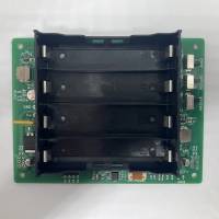
The RoverBase (Rover Baseboard) is an all-in-one power management and motor controller board for small skid-steer ground rovers. It is compatible with ArduPilot and PX4 flight controllers.
These features make the RoverBase ideal for small skid-steer ground rovers.
Features
The RoverBase integrates the following into a single board:
- 18650 battery power supply in a 2S2P layout (4 batteries required)
- 2x 5V, 3A power supplies. This includes a Pixhawk-compliant power supply for a flight controller.
- Voltage and current monitoring
- 2x 7.4V, 1.7A brushed DC motor controllers
- Power switches for major subsystems
- Battery charging port
Requirements
The Roverbase requires 4x 18650 batteries for power.
Specifications
General
| Specification | Value | Notes |
|---|---|---|
| Operating Temperature | -25° - 70° C | |
| Dimensions | 90x118x24mm | |
| Mounting dimensions | 4x M3 screws, 80x108mm |
Power Supply
| Power Supply | Nominal Voltage | Maximum Current |
|---|---|---|
| Flight Controller | 5.3V | 3A |
| AUX1 | 2S Battery, typically 6-8.4V | 4A |
| AUX2 | 5.1V | 3A |
Motor Controllers
The 2x brushed DC motor controllers (M1 and M2) are use the DRV8838 IC and can provide 1.7A continuous / 1.8A peak at the 2S battery voltage - typically 6-8.4V.
Setup
Hardware Setup
Batteries
4x 18650 batteries must be inserted as per the printed polarity markers in the battery holder.
Flight Controller
The flight controller's POWER port should be connected to the RoverBase's FC Power port with a 6-pin JST-GH cable. If the flight controller does not use JST-GH connectors, the J9 port be used instead and soldered with the appropriate connector.
AUX1, AUX2 power
The AUX1 and AUX2 power ports are used to power any accessories, such as servos or companion computers. The voltage and current rating of each port should be appropriate for the connected accessories.
Motors
Brushed DC motors should be connected to the Out1 and Out2 ports of each of the M1 and M2 motor controllers. Multiple (3x) motor outputs are provided if the user wishes to controller multiple motors from the same controller.
The motors are controlled via the M1/M2 PH/EN pins. These should be connected to the flight controller servo outputs, in accordance with the flight controller software settings.
Typically, the PH pins will connect to the AUX pins on the flight controller and the EN pins will connect to the MAIN pins on the flight controller.
Software Setup
For current and voltage monitoring, use the following parameters in ArduPilot:
BATT_AMP_OFFSET  1.650000
BATT_AMP_PERVLT  9.090000
BATT_LOW_VOLT    6.000000
BATT_MONITOR     4
BATT_VOLT_MULT   4.050000
The motor controllers will need to be set as “BrushedWithRelay” as per the documentation at https://ardupilot.org/rover/docs/common-brushed-motors.html
Using
Power switches
There are 3 power switches for turning power ON and OFF various subsystems. A nearby LED will display the state of each switch.
The switches are:
- MASTER - Provides master power, plus the AUX1 (7.4V) port and Flight Controller power.
- MOTORS – Enables motor controllers. Requires MASTERto be ON.
- AUX2 – Enables the AUX2 (5V) power output. Requires MASTER to be ON.
Charging
A charging port is provided, which can be soldered with the connector of your choice
SAFETY NOTE: The batteries must be charged at 2S (7.4V nominal) and the MASTER switch must be off during charging.
Versions
The following is a changelog of the hardware revisions of the RoverBase. The revision numbers are printed on the top side of the board.
V1.1
- Flight controller power uprated to 5.3V, as per Pixhawk standard
- Smaller board size
- Updated motor controllers
- Better power supply placement
V1.0
Initial release
